Timer And Contactor R Relay Diagram / Staircase Timer Wiring Diagram - Using On Delay Timer And Relay | Electrical Online 4u. Siemens overload relay wiring diagram. How to wire a timer relay. How to connect and set analog timer relay. Read or download pin timer relay diagram for free relay diagram at streamdiagram.summitacquanetwork.it. Crydom d2425 wiring diagram collection.
How to wire contactor block delay timer. Wiring diagram for timer and contactor. Air handler fan relay wiring diagram. Practice connect timer relay with start stop button,តម្លើង timer កំណត់ពេល. Figure 3.9 timing diagram 400a (electrically held).
Wiring Diagram For Dpdt Relay from simplecircuitdiagram.me This articles covers working and the major differences between contactor and relays. 12v relay with timer switch 4 steps. Practice connect timer relay with start stop button,តម្លើង timer កំណត់ពេល. Some more illustrations abide by. Omron safety relay wiring diagram gallery. Contactor wiring diagram with timer pdf. Siemens overload relay wiring diagram. File relay wiring diagram with an 8 pin cube.
Contactor relay coil wiring diagram.
Schneider 3 phase contactor wiring diagram. Crydom d2425 wiring diagram collection. Contactor switching time is higher than relay. Three phase motor control circuit difference between. How to wire a timer relay. 8 pin timer relay wiring diagram in urdu hindi. Wiring diagram for timer and contactor. How to wire contactor and overload relay. Engineering electrical diagram contactor and timer. Omron safety relay wiring diagram gallery. Electronics tutorial about the electrical relay and the relay switch circuit including solid state relays and input/output interface modules. 60 beautiful 2 pole contactor wiring diagram images. Wiring diagram car horn relay.
12v dc relay wiring diagram. Wire crossover symbols for circuit timer relay 120v wiring diagrams. Electrical contactor wiring diagram download. Relays and contactors both perform the switching operation. How to wire pin timers.
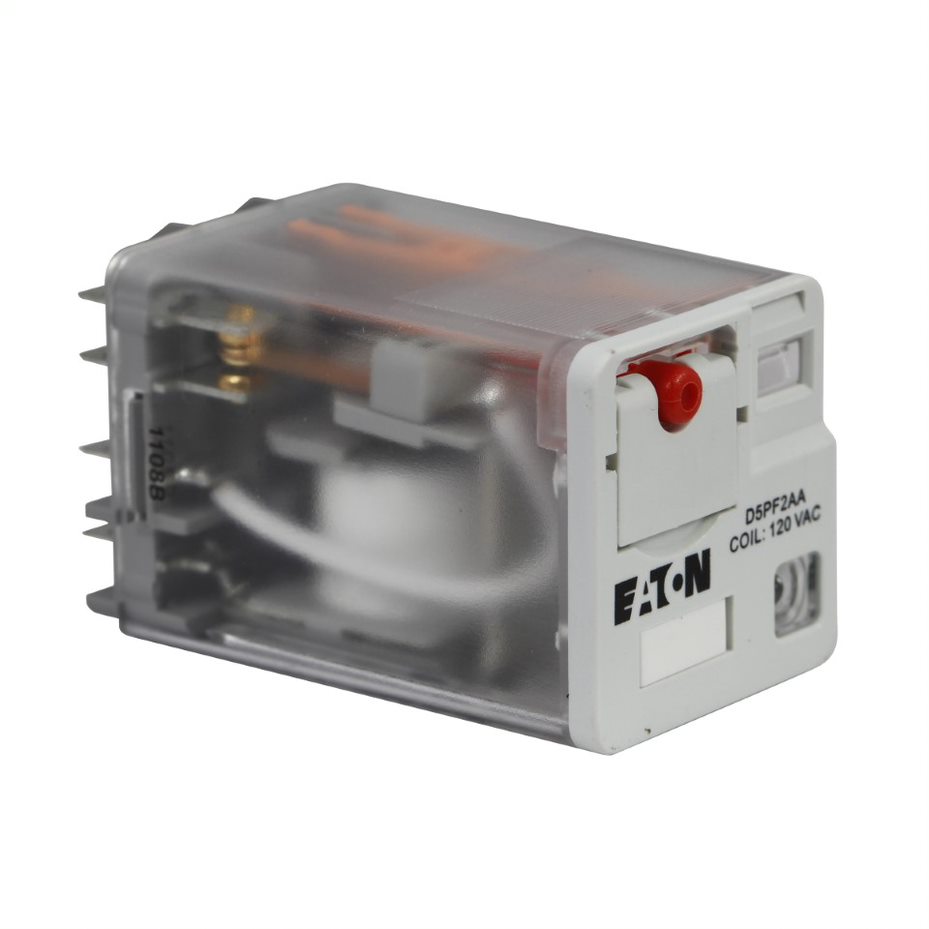
Control relays and timers from www.eaton.com Siemens overload relay wiring diagram. 12v relay wiring diagram 5 pin. How to wire a timer relay. Three phase motor control circuit difference between. Electrical diagrams contactor with timer. Circuit contactor relay diagrams are shots with symbols which have differed from place to place and possess altered after a while, but are now to a large extent internationally standardized. How to wire a contactor 8 steps with pictures. How to wire pin timers.
Circuit contactor relay diagrams are shots with symbols which have differed from place to place and possess altered after a while, but are now to a large extent internationally standardized.
Simple 4 pin relay diagram. How to wire contactor block delay timer. Air handler fan relay wiring diagram. A timer relay 120v wiring diagram is a symbolic representation of information using visualization procedures. Three phase motor control circuit difference between. A schematic, or schematic contactor relay diagram, is really a representation of the elements of a system utilizing abstract, graphic symbols rather than sensible pictures. 60 beautiful 2 pole contactor wiring diagram images. Single phase timer and contactor wiring diagram. On the circuit circuit diagram contactor relay, the symbols for parts are labelled that has a descriptor or reference designator matching that to the listing of components. 12v relay wiring diagram 5 pin. Switches are made to handle a wide range of voltages and currents; Three phase motor control circuit difference between. Dayton time delay relay wiring diagram gallery.
Dayton gear motor wiring diagram. Wiring diagram a wiring diagram is a simplified conventional pictorial representation of an electrical circuit. 12v relay wiring diagram 5 pin. Circuit contactor relay diagrams are shots with symbols which have differed from place to place and possess altered after a while, but are now to a large extent internationally standardized. Harley davidson sportster fuse box information.
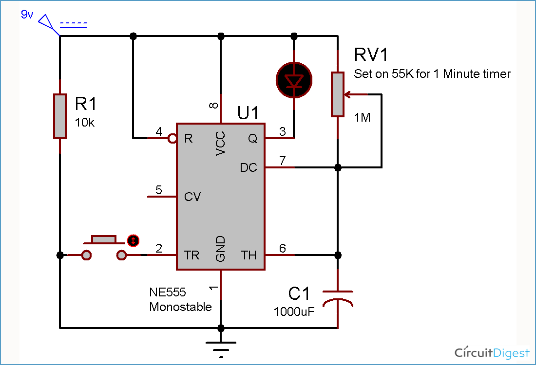
Time Delay Relay Wiring Diagram Download | Wiring Diagram Sample from faceitsalon.com Wire crossover symbols for circuit timer relay 120v wiring diagrams. Crydom d2425 wiring diagram collection. It shows the components of the circuit as simplified shapes, and the power and signal connections between the. Schneider 3 phase contactor wiring diagram. Wiring a 110v switch diagram fantastic stunning 120v relay. A 3 way switch has two terminals which have been possibly silver or brass coloured and a person terminal that may be dark coloured. Types, working and difference between them. File relay wiring diagram with an 8 pin cube.
How to wire contactor block delay timer.
A relay is a switch that is operated by electricity. Wiring diagram a wiring diagram is a simplified conventional pictorial representation of an electrical circuit. Circuit contactor relay diagrams are shots with symbols which have differed from place to place and possess altered after a while, but are now to a large extent internationally standardized. Dayton gear motor wiring diagram. Electrical contactor wiring diagram download. 12v dc relay wiring diagram. Some more illustrations abide by. 12v relay with timer switch 4 steps. 12v relay with timer switch 4 steps. Simple 4 pin relay diagram. Thousands of timer relay 120v wiring diagram methods exist. Air handler fan relay wiring diagram. A 3 way switch has two terminals which have been possibly silver or brass coloured and a person terminal that may be dark coloured.
Share :
Post a Comment
for "Timer And Contactor R Relay Diagram / Staircase Timer Wiring Diagram - Using On Delay Timer And Relay | Electrical Online 4u"


Post a Comment for "Timer And Contactor R Relay Diagram / Staircase Timer Wiring Diagram - Using On Delay Timer And Relay | Electrical Online 4u"